If you are having trouble with battery charging, continual burning or blowing of light bulbs, and other related electrical issues, this article will help with understanding and diagnosis. There are couple of things to know about early Kawasaki motorcycles and how the lighting & charging system work, because it is not conventional like most think.
This information is applicable to these specific models and is intended to be used along side either the factory service manual or equivalent Clymer manual.
G3SS, G3TR, G4TR, G5, F5, F6, F7, F8, F9
(1979 and later 100cc & 125cc bikes have a more conventional system)
All of these models are a 6 volt system. All replacement components must be 6 volt compatible.
First, not all models have a voltage regulator like more modern systems. Only a rectifier to convert the AC from the lighting & charging coils to DC. (The F5/F9 has a voltage regulator known as the SVR, but is only for regulating voltage for charging the battery, see appropriate section)
Second, there are two coils that deal with lighting & charging. This means there are 2 somewhat separate circuits. They function separately depending on "day" or "night" mode (key switch position).
Third, not every light bulb, switch, battery, or horn is on the same circuit or system all the time. This depends on "day" or "night" mode (key switch position).
Forth, The ignition system is completely separate from charging & lighting. These models do not require a battery or the lighting/charging system to run. The battery voltage (when installed) has no bearing on the quality of the spark, breaker points, CDI, or ignition coil's function. If you have no spark, it is not because of anything discussed on this page.
For the lights and charging on these models to function properly ALL the parts in the system have to be in place, and of the correct type. The operation of the lights and charging is dependent on each component contributing the correct resistance for the system. This means all of the bulbs must be the correct bulb, no "close enough" or substitutions can be made. Meaning, the bulb's watt rating must be correct. This also means corrosion in a bulb socket or poor connection can alter the resistance.
The battery must be of the correct capacity. Just because it can physically fit doesn't mean it will work. It must be of the correct amp hour for each model. See table below.
Any component failure or variation of the parts in the system can cause overcharging or undercharging of the battery, as well as dim or blowing bulbs. It all depends on where and what fault is.
Common problems:
Bad battery (internal damage, low electrolyte level, wrong type)
Burned out bulbs in the speedometer/tach housing (often overlooked)
Incorrect bulbs in the speedometer/tach housing
Tail/Brake light bulb (dual filament bulb), Tail light filament is on a different circuit from the brake light filament. (one burnt out)
Less common problems:
Faulty rectifier (allowing AC current into the system or battery voltage back to the charging/lighting coils)
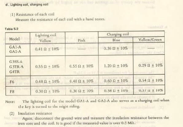
Degraded lighting & charging coils (incorrect resistance from degraded insulation, see chart for testing below)
Horn stuck "on", the horn works by a diaphragm rapidly moving between two contacts via a electro magnet coil. If the horn is stuck in the closed position this can create a constant closed connection reducing resistance in the coil within the horn and if the button is pressed for extended periods of time this can demand high voltage through the system and usually blows the main fuse at the battery.
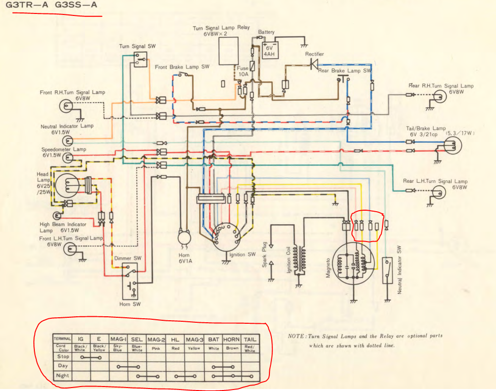
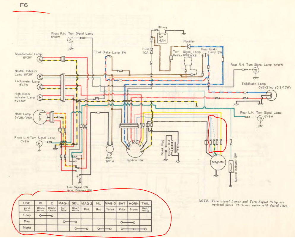
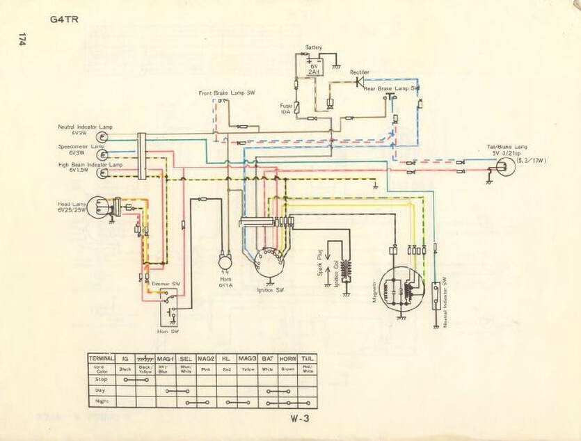
Food for thought. On these models there is a second tap on the charging coil that is un-used unless undercharging or over charging of the battery becomes a problem. This can happen when running excessive daytime or night time operation versus the factory configuration as illustrated on the wiring diagram. (See below examples)
The factory & Clymer manuals discuss or explain this poorly. The Cylmer (M350) actually is a little more coherent, however omits describing which models this applies to specifically where the factory lists the F6 & F8, but negates the G3SS, G3TR, G5 even though they function the same. Only conclusion I can come up with is the older GA1 and GA2 models do not have this function and the editor, just negated the newer "G" models all together since the G3's were based on the GA's.
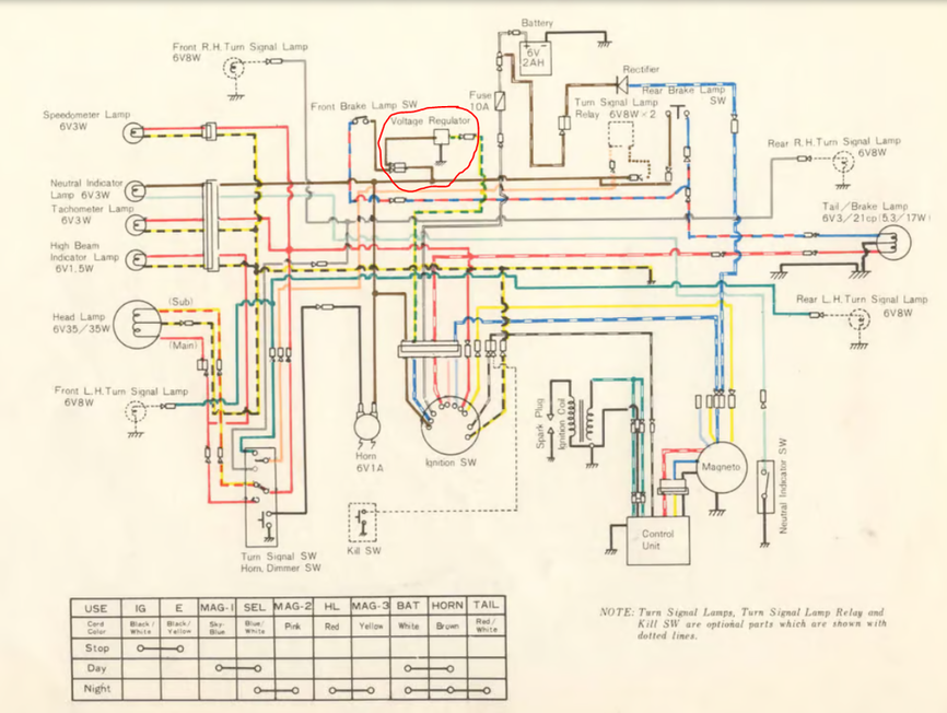
Kawasaki F5 & F9 SVR (voltage regulator)
As crazy as this sounds, the voltage regulator does not control the voltage to the lights when the lights are operating. This is explained in the Clymer & Factory service manual. Neither explanation's are anywhere near where the section that talks about the voltage regulator/SVR function and testing in the manual. Which is why it is easily missed. The Clymer's wording is easier to read and understand than the factory service manual's broken English translations.
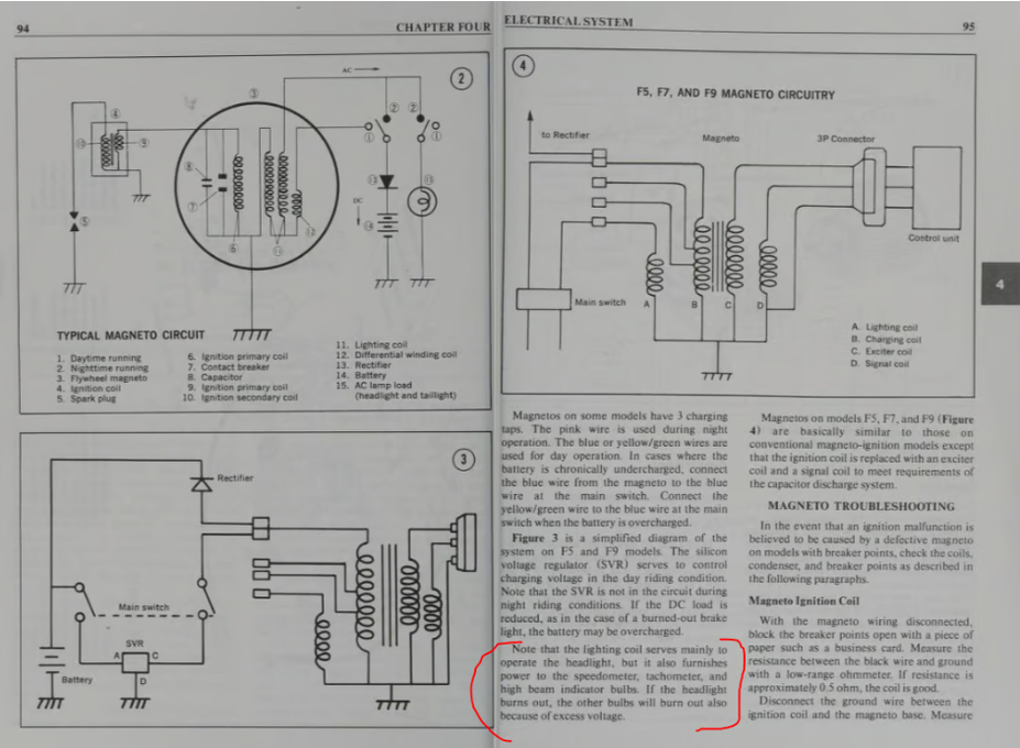
The headlight, taillight, high beam, speedo & tach lights, are all powered directly from the Lighting coil. The battery is in the system as well, but only as a buffer indirectly. The current This is why the lights dim a little at idle because the load is carried almost completely by the battery in "nighttime" operation. In short, nighttime operation voltage is almost exclusively regulated by the resistance of the entire system. Take one component out or change the resistance of that system and the voltage will go up as it finds a different path to ground (or going to zero in the case of switching the lights off)
Side note: The HORN is on both day & night systems, but is not considered here because it would only see intermittent use and load on the system.
In "daytime" operation the lights are not part of the system and then the power from the charging coil goes directly to the voltage regulator only to charge the battery. The brake light and neutral indicator are also part of the circuit because those are needed in both daytime & nighttime operation. This means those bulbs need to be present or the SVR will overcharge the battery as the SCR will see less resistance and open the gate. This system relies on the balance of load (resistance) of all the parts for everything to function correctly. Note: The turn signals and relay would be in this system if they are installed (optional on some models)
Yellow wire= lighting coil (Red wire from switch for nighttime)
Blue/White= Charging coil (White, Brown, from switch for daytime)

