
KAWASAKI Service manual & wiring diagrams
This page is a collection of hard to find information, procedures, tests, and specifications for vintage Kawasaki motorcycles.
|
Oil Pump Air bleeding & output test
for SuperLube & Injectolube systems. 1. Remove oil pump check valve outlet pipe (the banjo bolt, see Fig 1) 2. Use 20:1 premix in the tank before starting the engine. 3. Remove the cable for the oil pump so it can be opened fully for the test. 4. With some wire open the pump cam to full throttle position. 5. Start engine and run at aprox. 2,000 RPM. 6. With a stopwatch run the engine for 3 minutes while collecting the oil from the oil pipe. Specifications are listed for each model in the table. *For models not listed, use the closest appropriate model displacement (F6 125cc, F7 175cc..) as Kawasaki only made minor revisions over the years but the oil pump output will be similar and should be within a similar output. Example: G-Series output specification would be similar for later 80-100cc models such as the KE/KV/KM100, MC1, KD80, ect.. as they share similarities. |
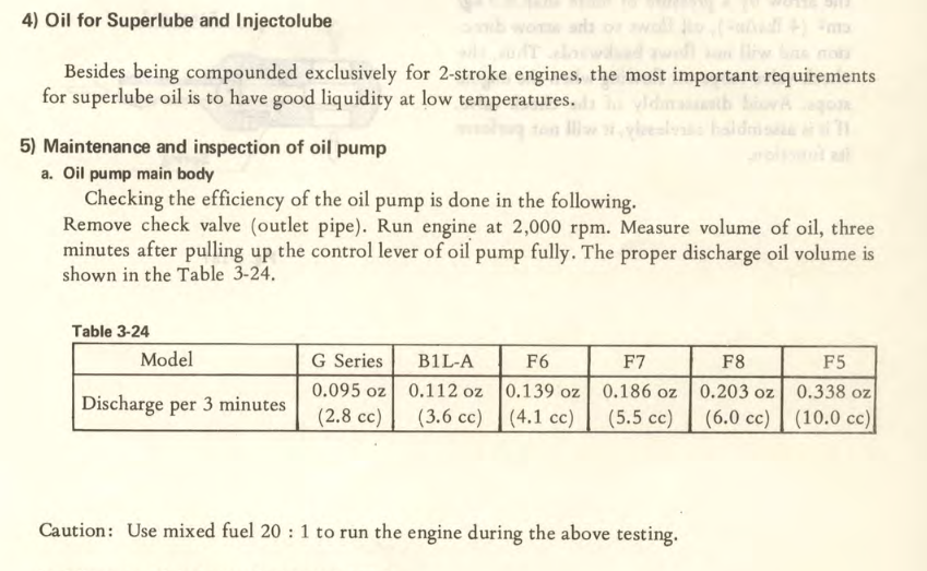
Oil Pump priming & pump output test & table specifications
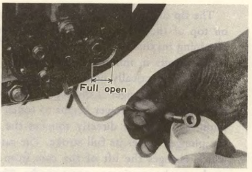
Fig 1. Oil pump pipe banjo bolt removed
|
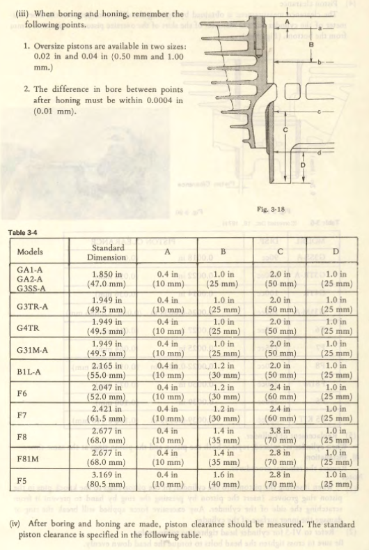
Kawasaki piston size bore and over size specification chart
Kawasaki cylinder bore service limit
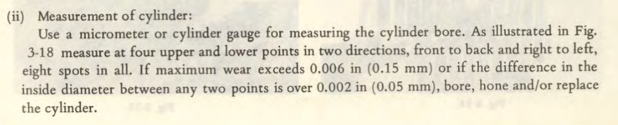
Measurement of the cylinder (see chart below for specific model). If any measurement deviates more than 0.05mm between any measured point OR if the of of the points exceeds 0.15mm over the STANDARD bore the cylinder needs to be bored to the next .5mm size. If the initial measurement is already over the 1mm (commonly referred as 2nd over)" service limit of the cylinder. The cylinder needs to be replaced.
Example: F5 standard bore is 80.5mm. If measurements at points A-D in the cylinder measure 80.66. The cylinder needs to be bored .5mm (1st over) or 81mm and a .5mm over piston & ring combo must be used.
Example: F5 standard bore is 80.5mm. If measurements at points A-D in the cylinder measure 80.66. The cylinder needs to be bored .5mm (1st over) or 81mm and a .5mm over piston & ring combo must be used.
Kawasaki cylinder bore size chart & mesurement
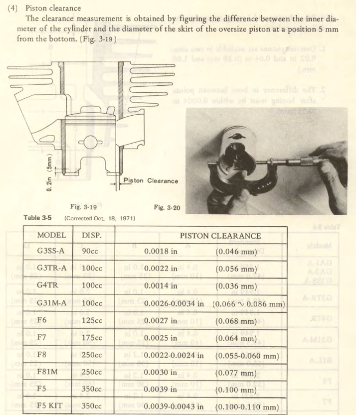
Kawasaki piston clearance chart
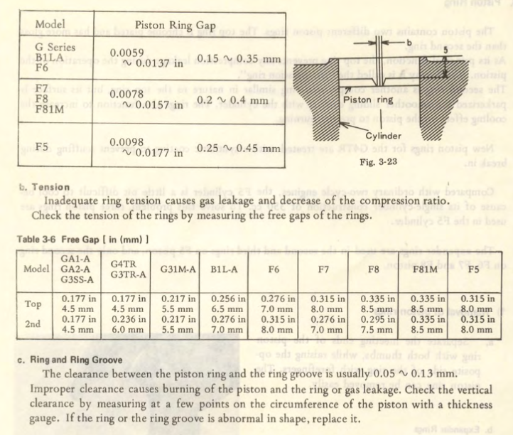
Kawasaki Piston ring gap measurement
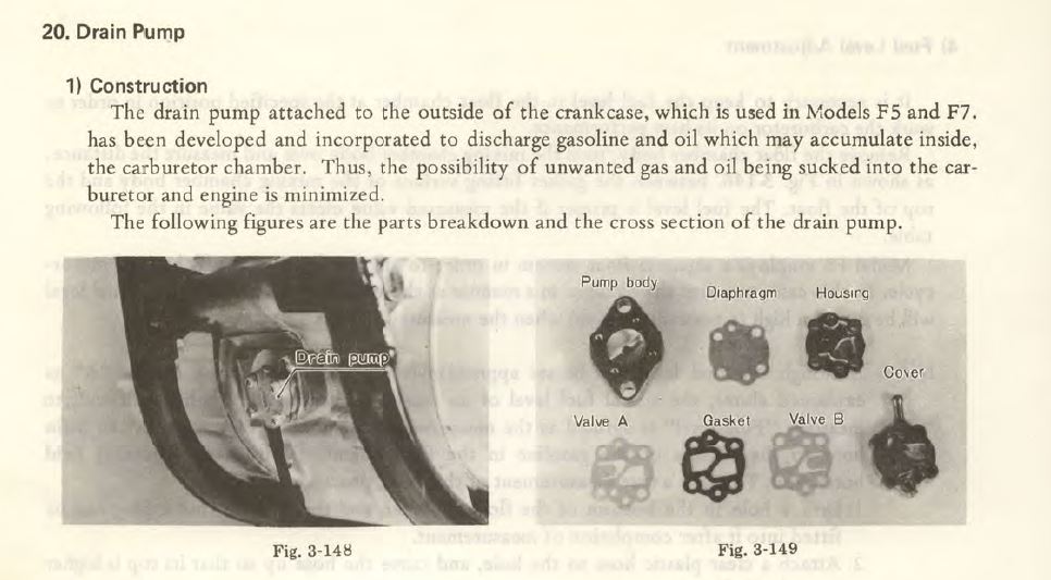
Kawasaki F5/F9/F7 drain pump explanation
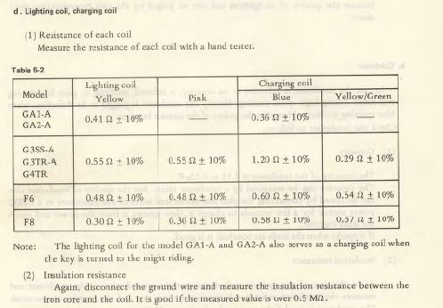
Kawasaki GA1 GA2 G3 G4 F6 F8 lighting and charging coil test values
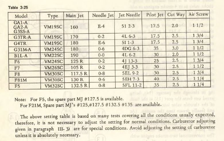
Kawasaki GA1 GA2 G3TR G3SS F6 F7 F8 F81M F5 carburetor settings
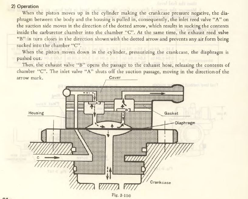
Kawasaki F5/F9/F7 drain pump explanation
Lighting & Charging diagnosis
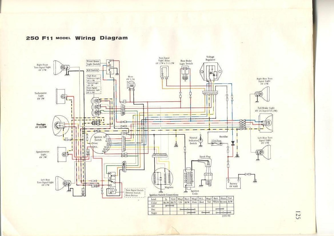
73-75 Kawasaki F11 wiring diagram
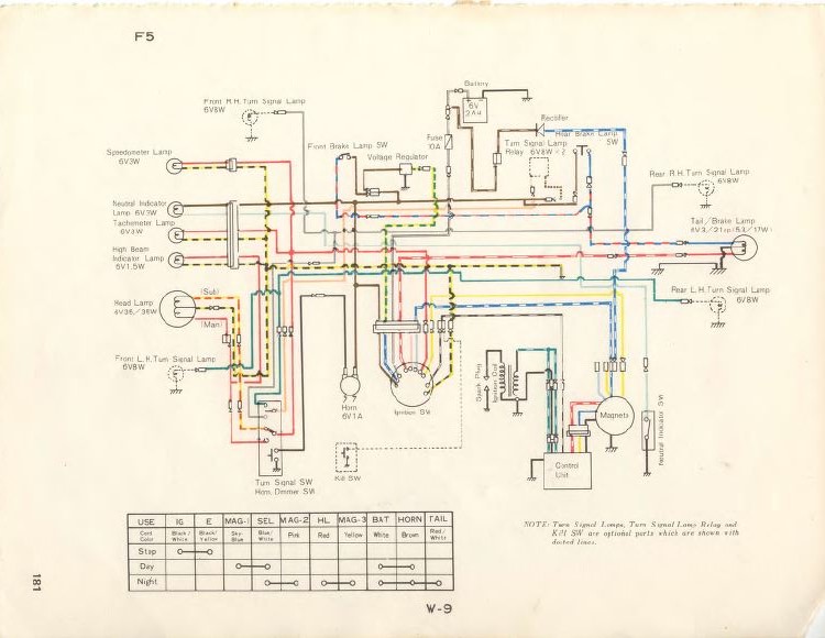
70-71 Kawasaki F5 wiring diagram
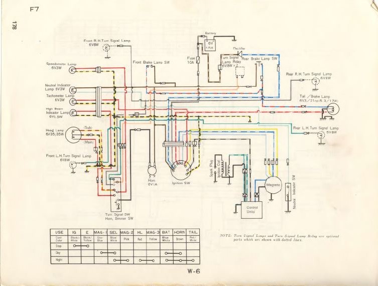
71-73 Kawasaki F7 wiring
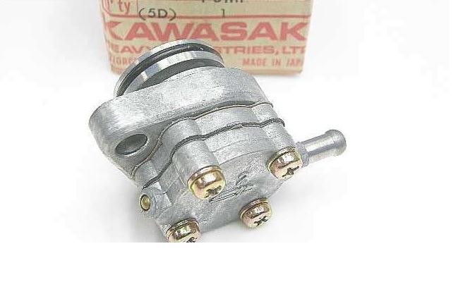
It is good practice to remove and block off this device, it creates a vacuum leak when it fails

Kawasaki B1L-A (125) wiring

Kawasaki G4TR 100 wiring
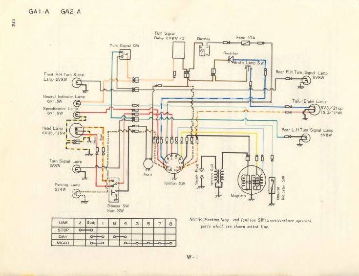
Kawasaki GA1 and GA2 wiring
The Kawasaki "drain pump" F7/F5/F9
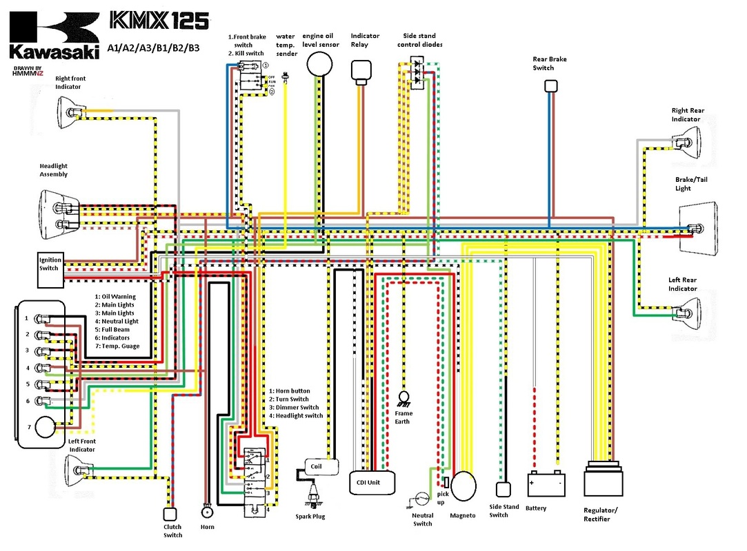
Kawasaki KMX 125 wiring diagram (Euro model not imported to the US)
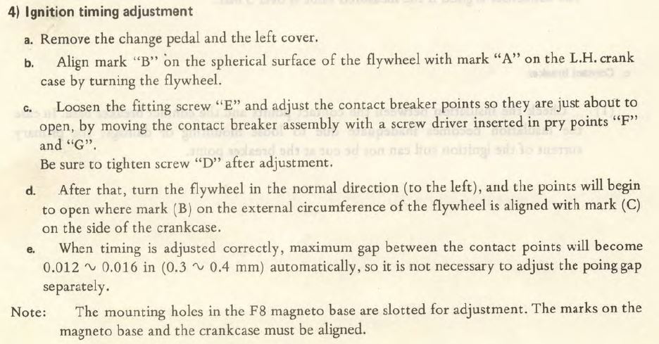
Kawasaki G3, G4, F6, F8 ignition timing adjustment proceedure
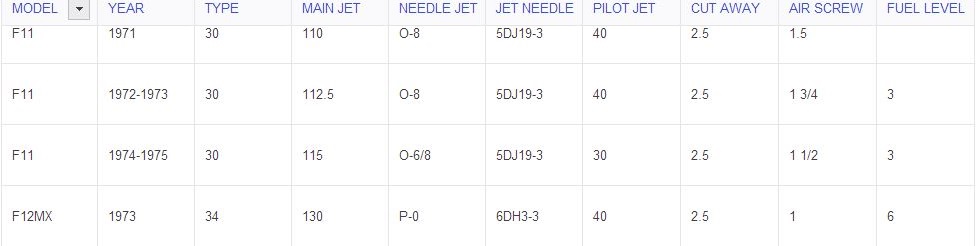
Kawasaki F11 and F12MX carburetor specs
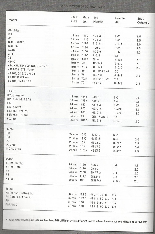
Carburetor specs for various Rotary Valve Kawasaki models.
Kawasaki Fork oil quantity for the following models. B1L-A,G-series, G4TR, G31M, F6, F7, F8, F81M, F5 (F9)
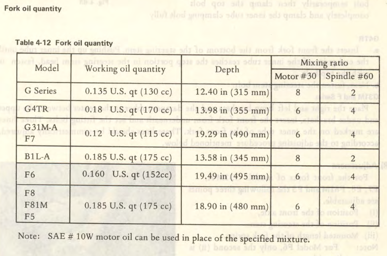
Fork oil quantity chart
Kawasaki F5, F9, F8, F81M cylinder head torque specs:
8mm (small bolts) 18 ft-lbs
10mm (large bolts) 25 ft-lbs
8mm (small bolts) 18 ft-lbs
10mm (large bolts) 25 ft-lbs
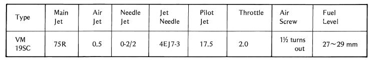
Kawasaki KE100 carburetor specs
1974-1976 Kawasaki KX125 wiring diagram
Kawasaki KE100 Carburetor specs
Carb type Main Jet Air jet pilot jet Air screw Fuel level
VM19SC 75 .05 17.5 1 1/2 turns 27-29mm
Carb type Main Jet Air jet pilot jet Air screw Fuel level
VM19SC 75 .05 17.5 1 1/2 turns 27-29mm
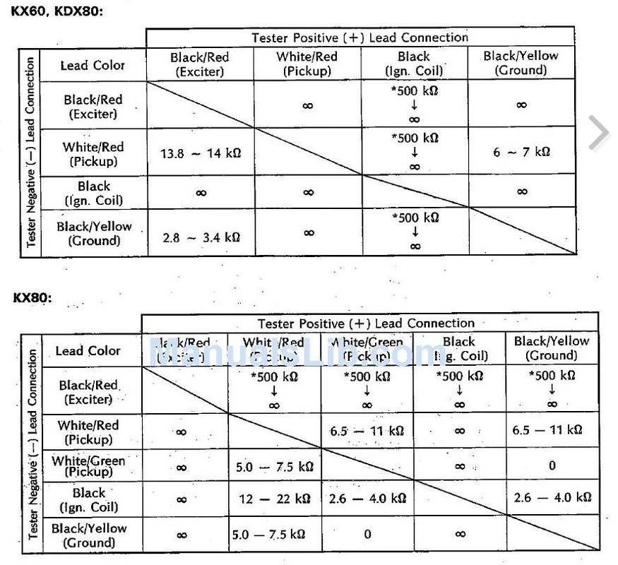
Kawasaki KX80 KX60 KDX80 CDI testing
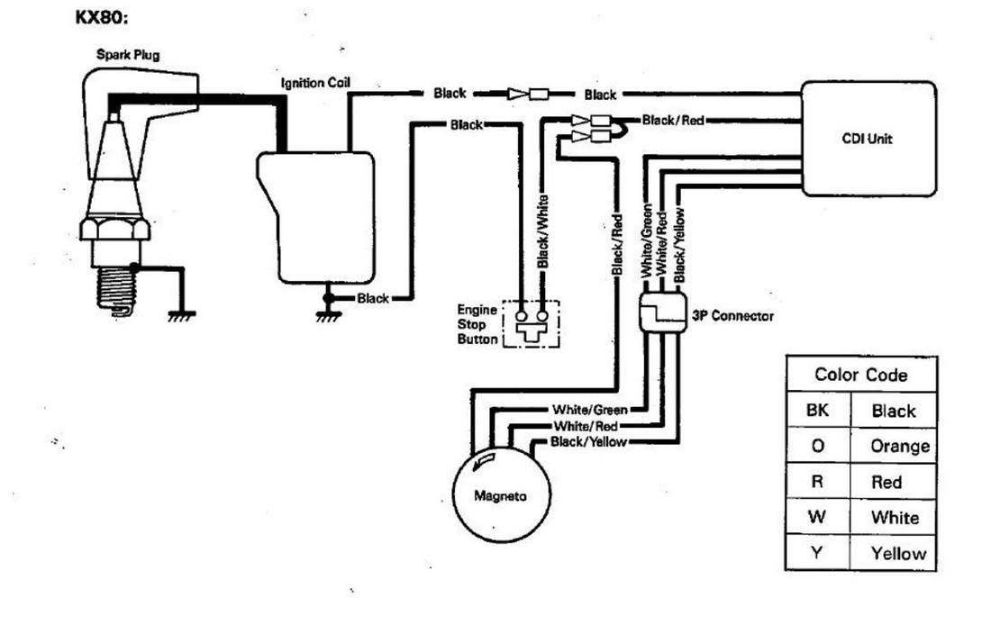
Kawasaki KX80 wiring
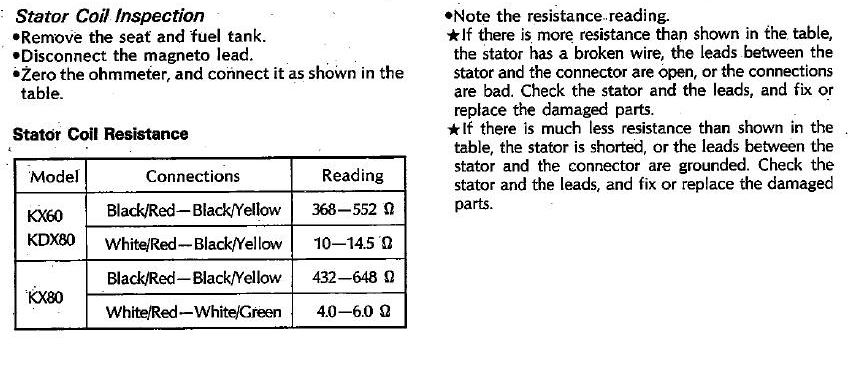
Kawasaki KX80 KX60 KDX80 Stator coil testing
Carburetor settings chart (specs also found on the appropriate model pages as well) covers these models. GA1A, GA2A, G3SSA, G3TRA, G4TR, G31M, B1LA, F6, F7, F8, F81M, F5
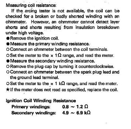
Kawasaki KX80 KX60 KDX80 Ignition coil test
Lighting & charging coil test values for Kawasaki models GA1A, GA2A, G3SSA, G3TR, G4TR, F6, F8
Kawasaki F11 ignition tests
Kawasaki F21M wiring (other models noted)
|
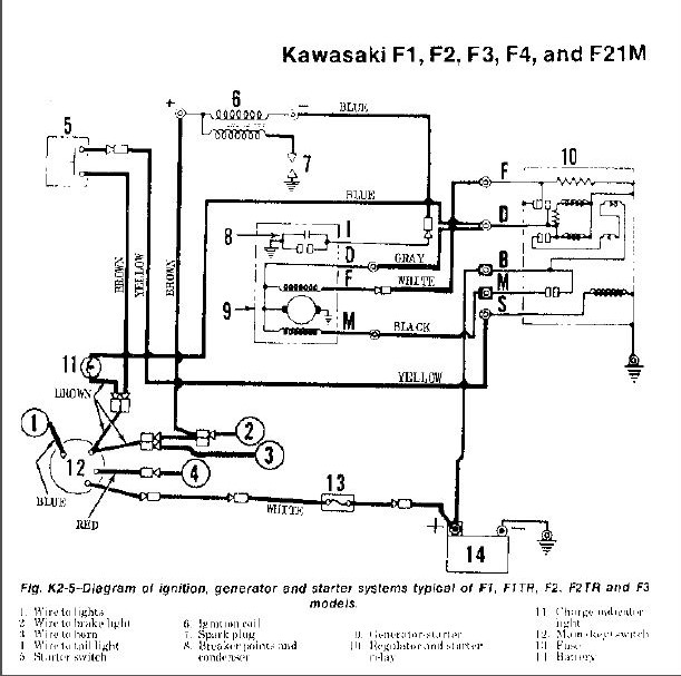
Key for Fig K2-5 Diagram of ignition, generator, and starter systems typical of Kawasaki F1, F1TR, F2, F2TR and F3 models. Including F21M
Kawasaki F1, F2, F3, F4 and F21M wiring diagram (see key)
|
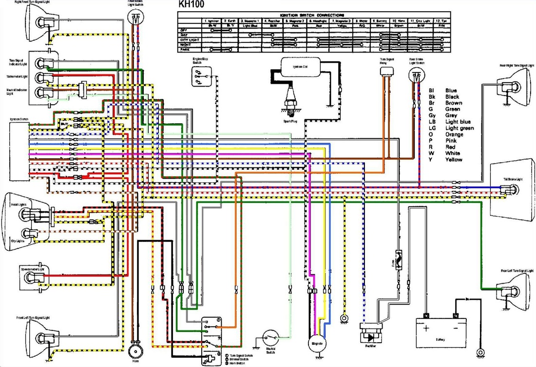
Kawasaki KH100 wiring diagram
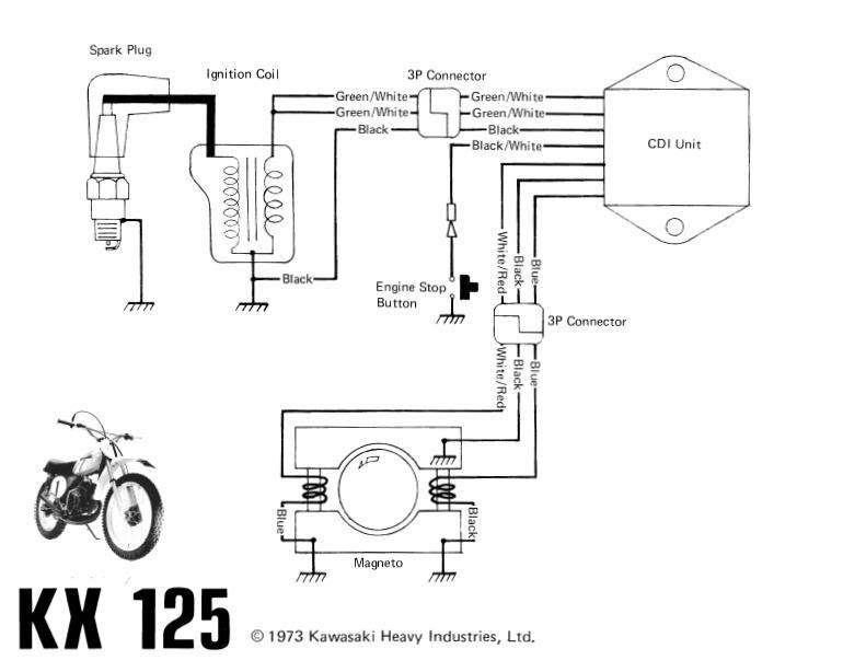
1973 Kawasaki KX 125 wiring diagram
Kawasaki F11 250 wiring diagram
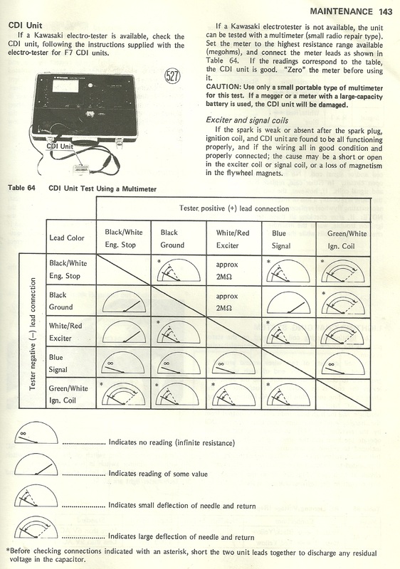
Kawasaki CDI unit testing procedure for KE models (may apply to other models)
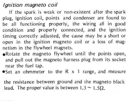
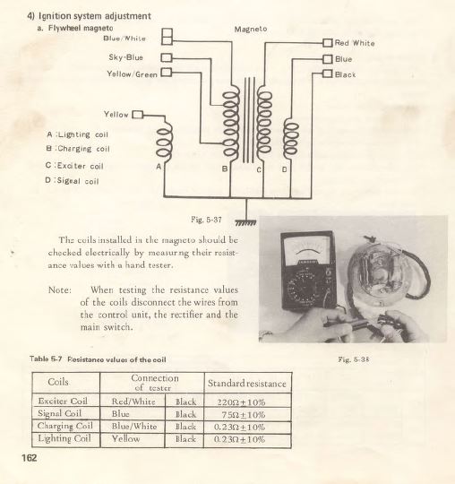
Kawasaki KE100 (KM100) points style magneto coil testing procedure
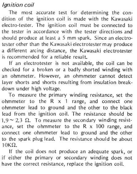
Kawasaki KE100 (KM100) Ignition coil testing
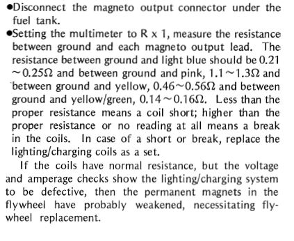
KE100 (KM100) charging coil test procedure
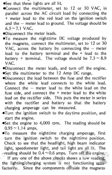
KE100 (KM100) Charging tests
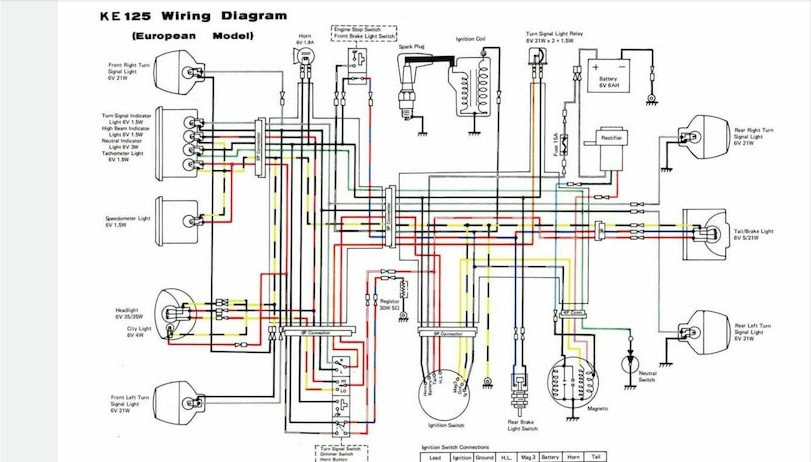
KE125 Wiring diagram (Euro model)
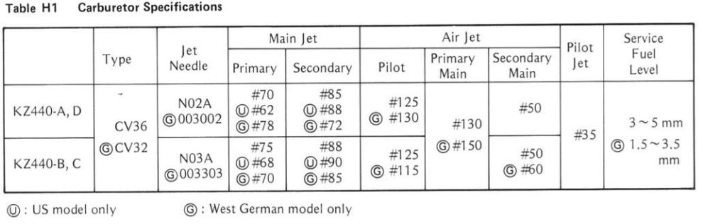
KZ440 carburetor specifications
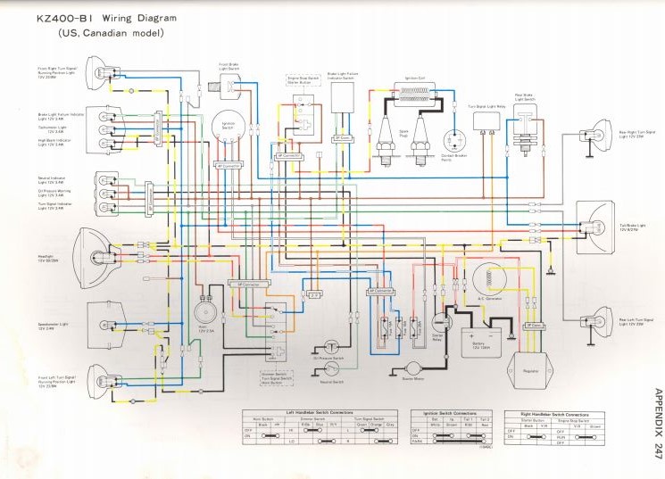
Kawasaki KZ400 B1 wiring
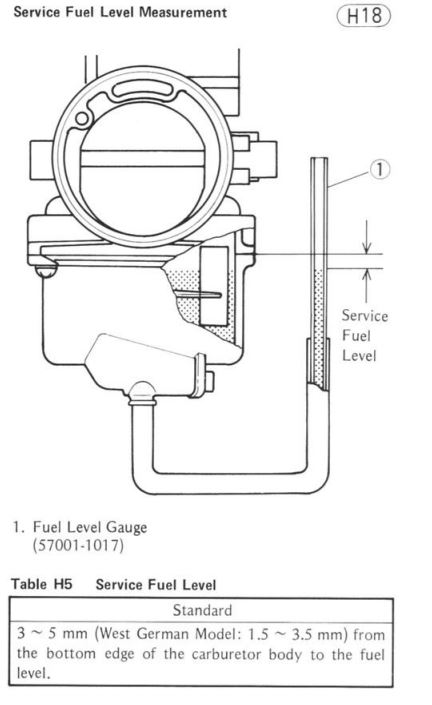
KZ440 float height measurement
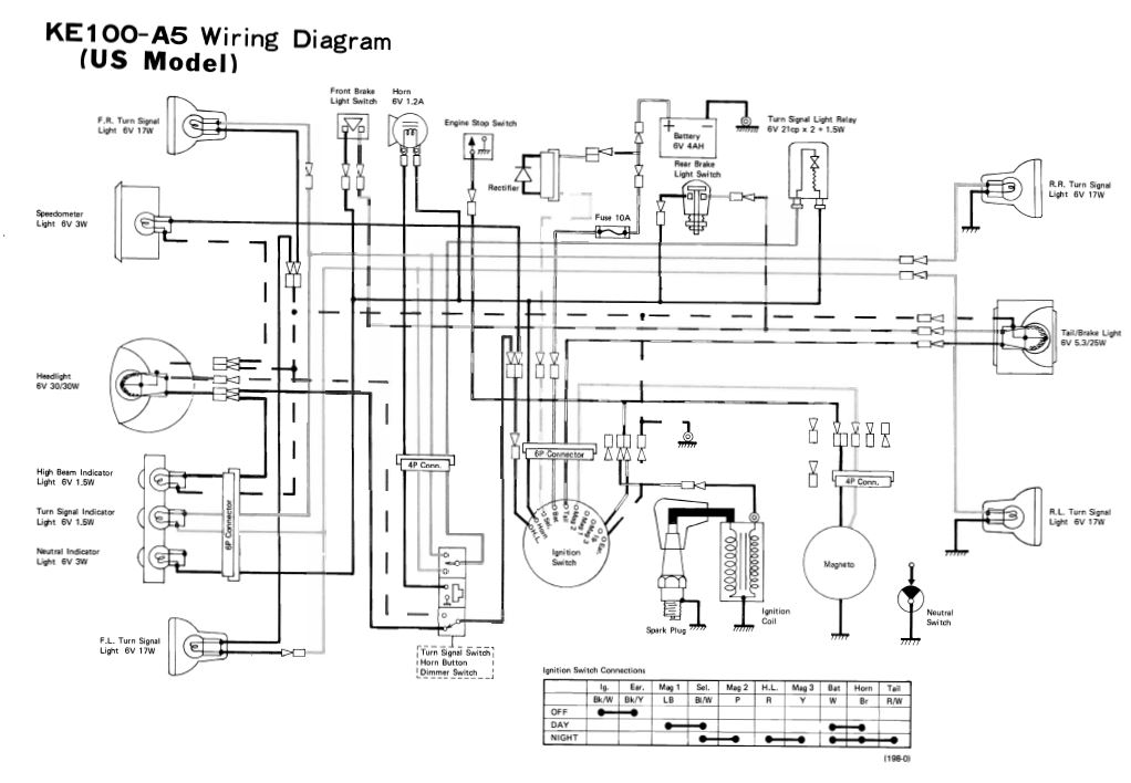
Kawasaki KE100 (KM100) wiring diagram
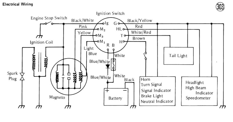
Kawasaki KE100 (KM100) ignition switch wiring detail
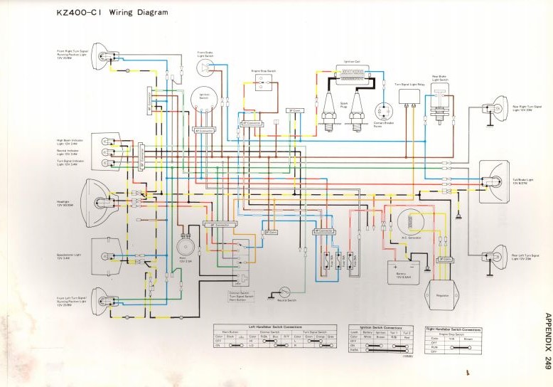
Kawasaki KZ400 C1 wiring
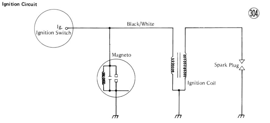
Kawasaki KE100 (KM100) ignition circuit
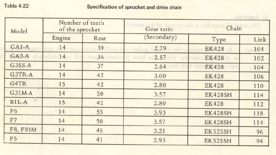
Kawasaki rotary valve singles standard chain and sprocket specifications
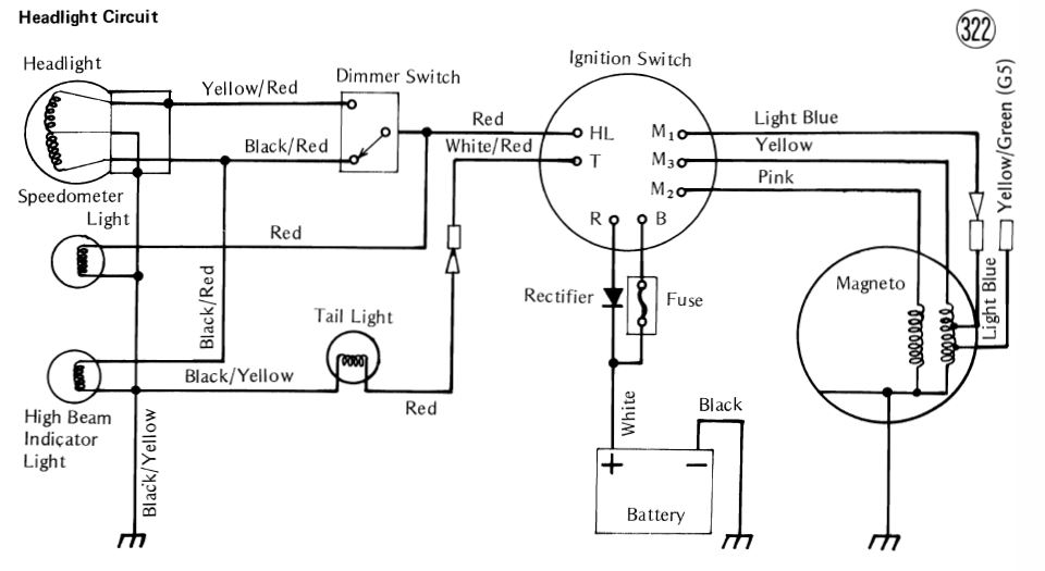
Kawasaki KE100 (KM100) headlight/battery circuit
Kawasaki F5 F9 F7 signal exciter coil testing values
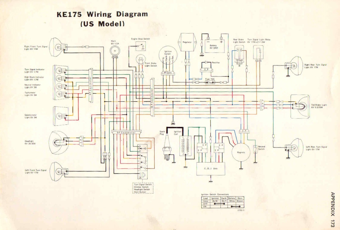
Kawasaki KE175 wiring diagram
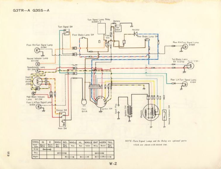
Kawasaki G3TR and G3SS wiring
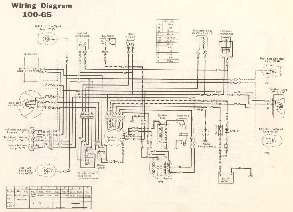
Kawasaki G5 100 wiring
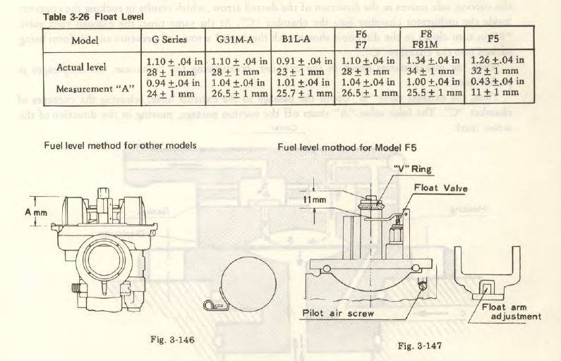
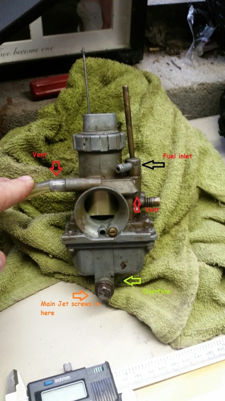
Kawasaki G series F series carburetor float level settings
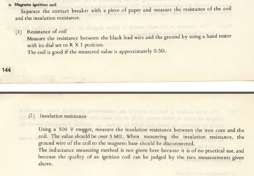
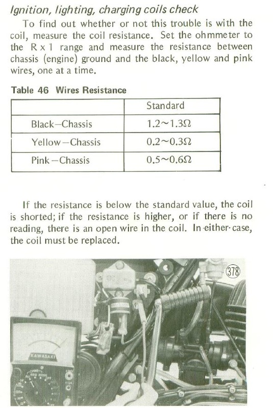
Kawasaki G series, F6, F8 magneto coil test procedure
Ke125 Carburetor
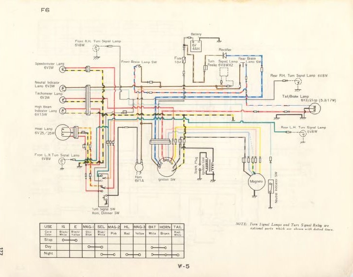
71-73 Kawasaki F6 wiring
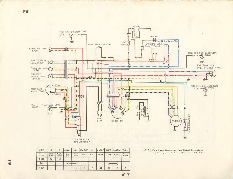
Kawasaki F8 wiring
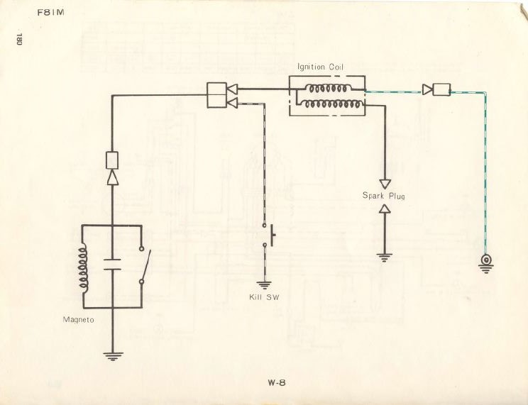
1971 Kawasaki F81M wiring diagram
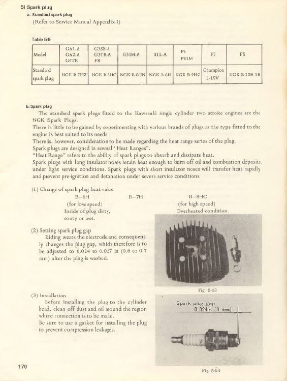
70-73 Kawasaki standard spark plugs, G series, B1L, F series (rotary valve models)
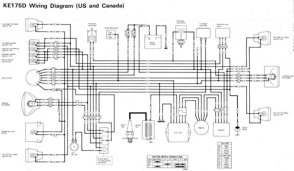
KE175 Wiring diagram
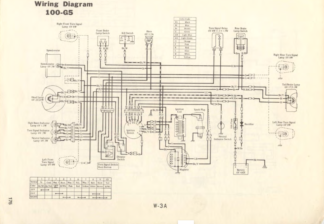
Kawasaki G5 wiring
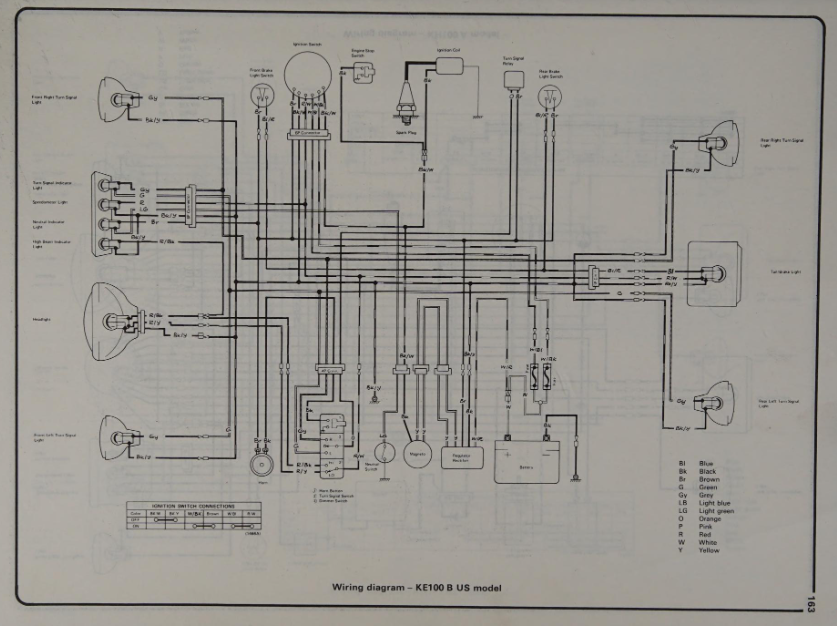
KE100 B models wiring diagram
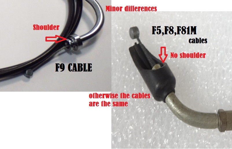
Minor cable differences between F5/F8/F81M and F9 throttle control (oil pump) cables.